· 14 min read
Planet Texture Baking in Unity, Part 1: Equirectangular Textures
Setting up texture baking output inside Unity with a Shader Graph. Converting 3D planet position to spherical coordinates. Editor scripts for texture capture from a material.
Procedural Planet Shaders and Texture Baking
There are many different approaches to procedural planet generation: mesh-based deformation, volumetric raymarching, advanced mesh partitioning techniques for LOD and landable planets. Here, I’ll show you a simple shader-based approach for Unity’s URP. You might use this in a space strategy game where you won’t be landing on planets but want to display many unique planets on a star map.
Procedural shaders provide infinite (albeit similar) variations and instant real-time customization. But they come with a high cost on GPU performance. On modern GPUs, this is manageable - you can get good framerates without perfectly optimized shaders. But it’s still wasteful to recalculate the surfaces of static planets every frame, and very complex shaders can end up impacting performance significantly.
Traditional workflows may have you design materials in Blender, then bake their outputs to textures for importing in Unity. That works, but switching between tools costs time, and Blender’s lighting settings and exported textures don’t always remain consistent when imported in Unity. Baking inside Unity will get you planet textures that look 1:1 with the procedural shader texture but at a fraction of the performance cost.
In the first part of this tutorial series, we’ll set up equirectangular texture baking for a simple Earth-like planet shader’s color texture. Future tutorials will include more advanced techniques like cubemap baking, normal and other mask baking, and flowmaps for gas giants and stars.
Project Setup
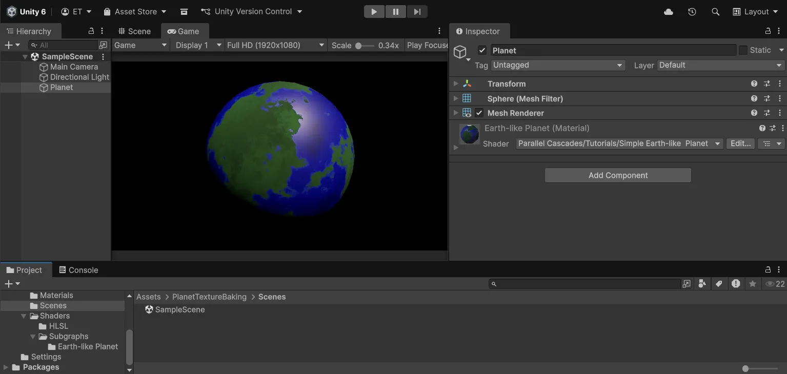
To get started, I’ve provided you with a Unity project that has the foundation for building a procedural texture baking utility. It’s built with Unity 6000.0.64f1 and the Universal Render Pipeline (URP). This includes a simple Earth-like planet shader in a blank scene that we will modify to add texture baking functionality.
You can clone the project from this Github repository, or download the .unitypackage from the Releases section and import it into your own project. If you just want to see the completed files, you can also get the completed project from the same repository.
For the full advanced procedural planets system, take a look at the Procedural Planet Generation asset on the Unity Asset Store.
Starter Scene
Open the provided sample scene to get started:
Planet Shader
The planet shader is built with Shader Graph. Among other benefits, I prefer making shaders with Shader Graph because the visual node previews enable quick debugging and experimentation.
If you’re unfamiliar with Shader Graph, refer to the official Unity documentation.
We will edit this shader to add texture baking functionality. Open the Simple Earth-like Planet Shader Graph.
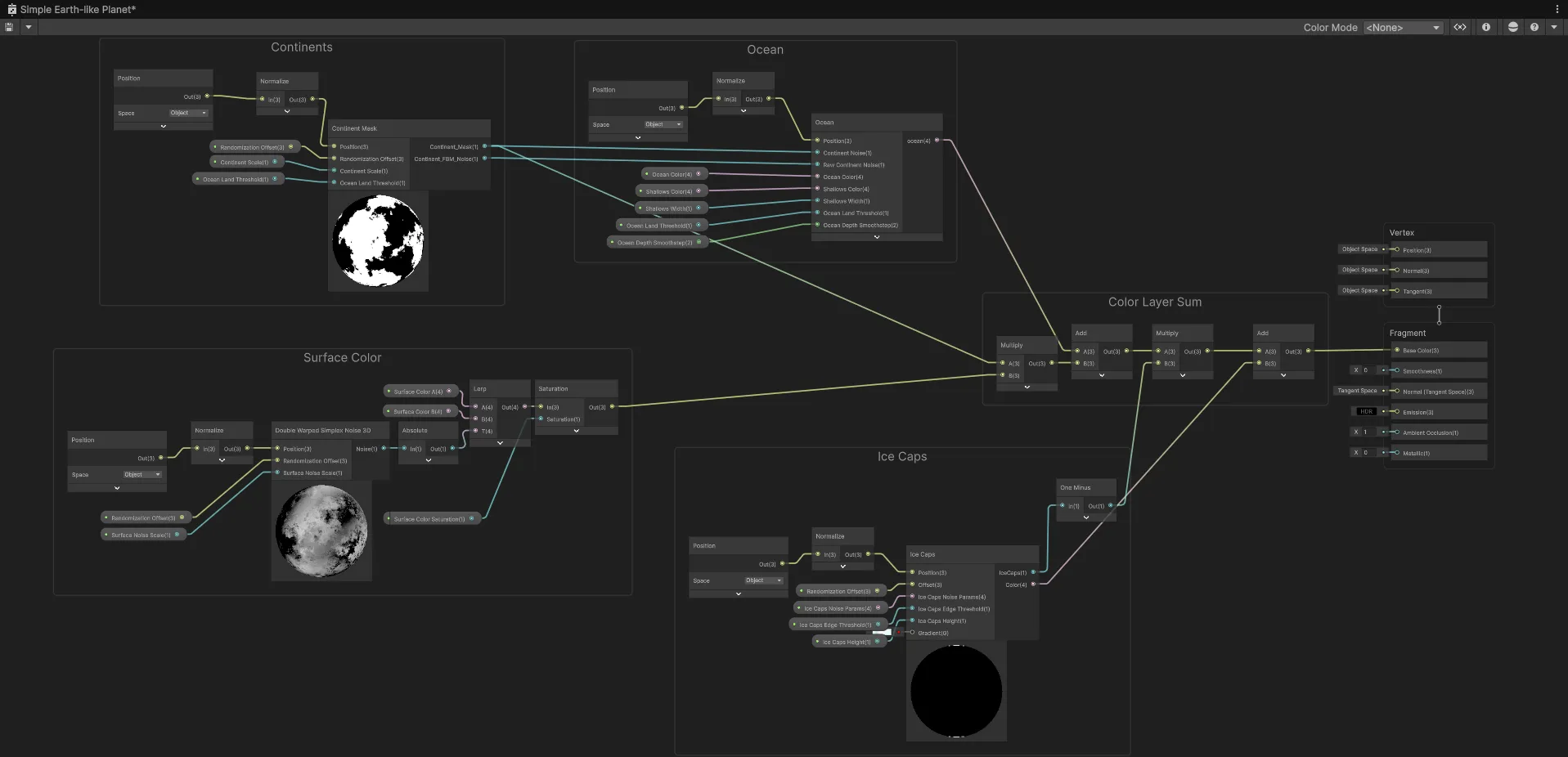
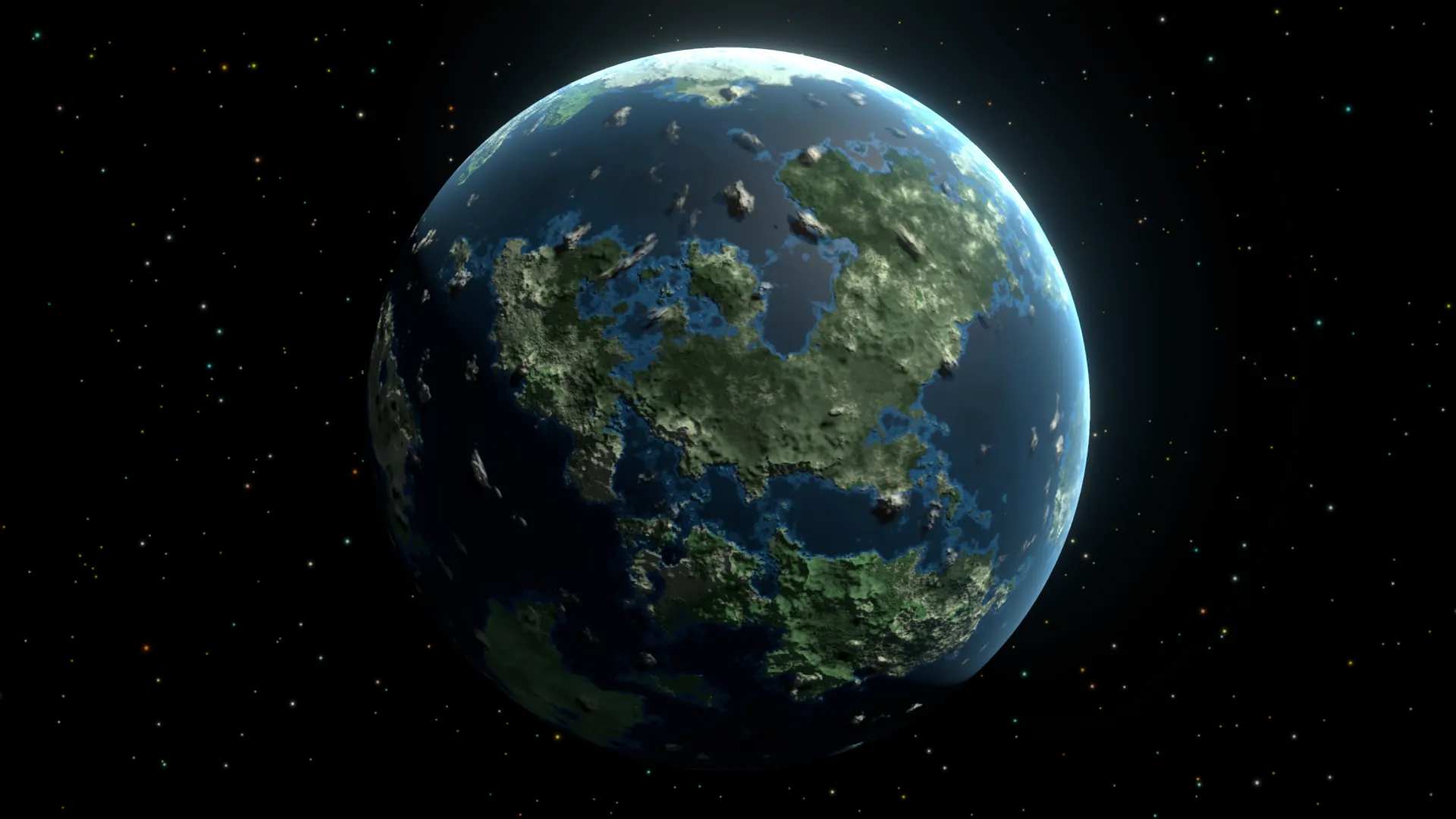
You can see the different layers that make up the planet surface: continents, oceans, ice caps, and surface color. This is a very simplified version of a planet shader that will allow us to focus on the texture baking process.
The foundational building blocks of procedural planet shaders are 3D noise functions that we manipulate in different ways to get natural-looking terrain features. If you want to learn more about noise functions, I recommend the following resources: Inigo Quilez - Fractal Brownian Motion and Catlike Coding - Pseudorandom Noise
The main performance cost of the procedural shader comes from these noise functions being calculated every frame for every pixel on the screen that covers the planet mesh.
Shader Performance
We need to measure the baseline performance before baking, to see what improvement we will bring later. Testing on a GTX 3060, we set the game view to 4K resolution to have the largest performance impact:
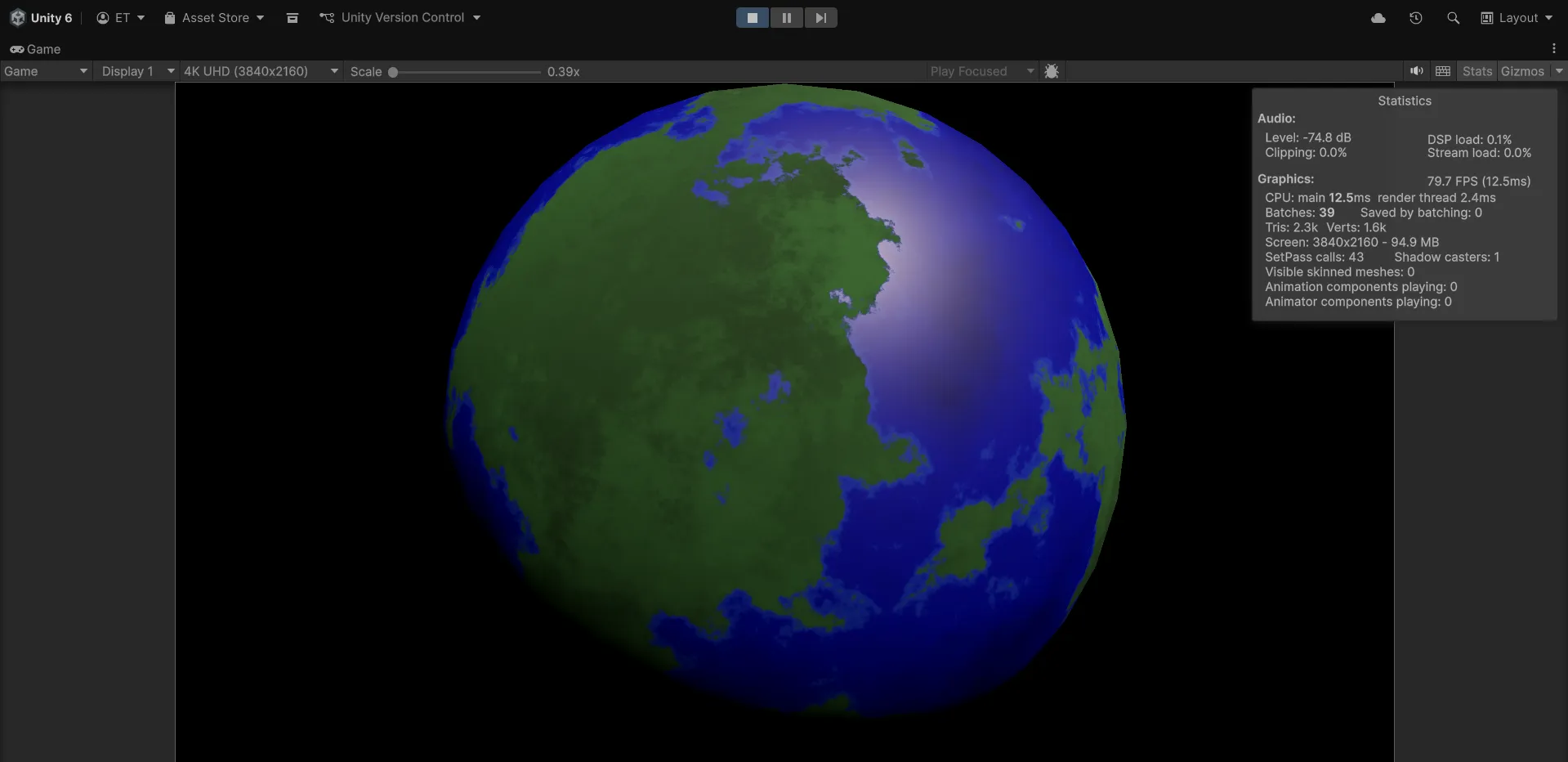
So we get around 80 FPS, or about 12 ms per frame, when a simple static planet fills the screen.
This is before adding more complex detail to the planet. Heightmap mountains require another layer of noise. If we want to have procedural normals, we will need to apply smoothing by taking multiple samples for the noise functions per pixel. All this adds up quickly.
Replacing these procedural noise calculations with a texture sample will improve performance significantly. This tutorial will show how to set up the texture baking for the surface color and then sample it as a texture. The same approach works for heightmaps, smoothness, metallic, emission maps, etc.
Texture baking
Baking Outline
The texture baking technique inside Unity is the following:
We will apply our planet material to a temporary flat quad in front of an orthographic camera so that it fills the camera view. Then we use a render texture to capture that camera output, read back the pixels into a Texture2D, and save that to disk as a PNG file.
Flat Quad UV Mapping
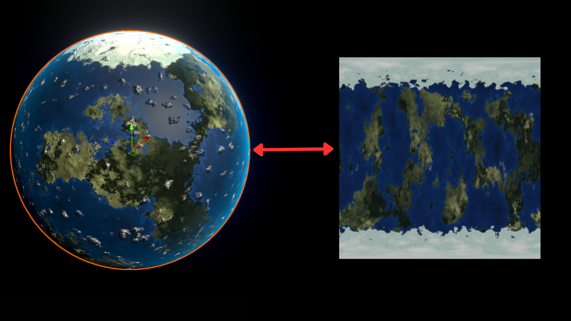
If we place our material on a quad, we get this stretched-out and distorted texture:
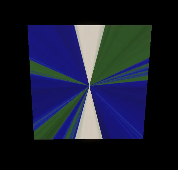
In the planet shader, our noise functions receive the normalized 3D Object Position of each point on the sphere’s surface. But the flat quad only has 2 dimensions and normalizing object position.
So we will need to figure out the mappings between the quad’s 2D UV coordinates and the 3D positions on the sphere.
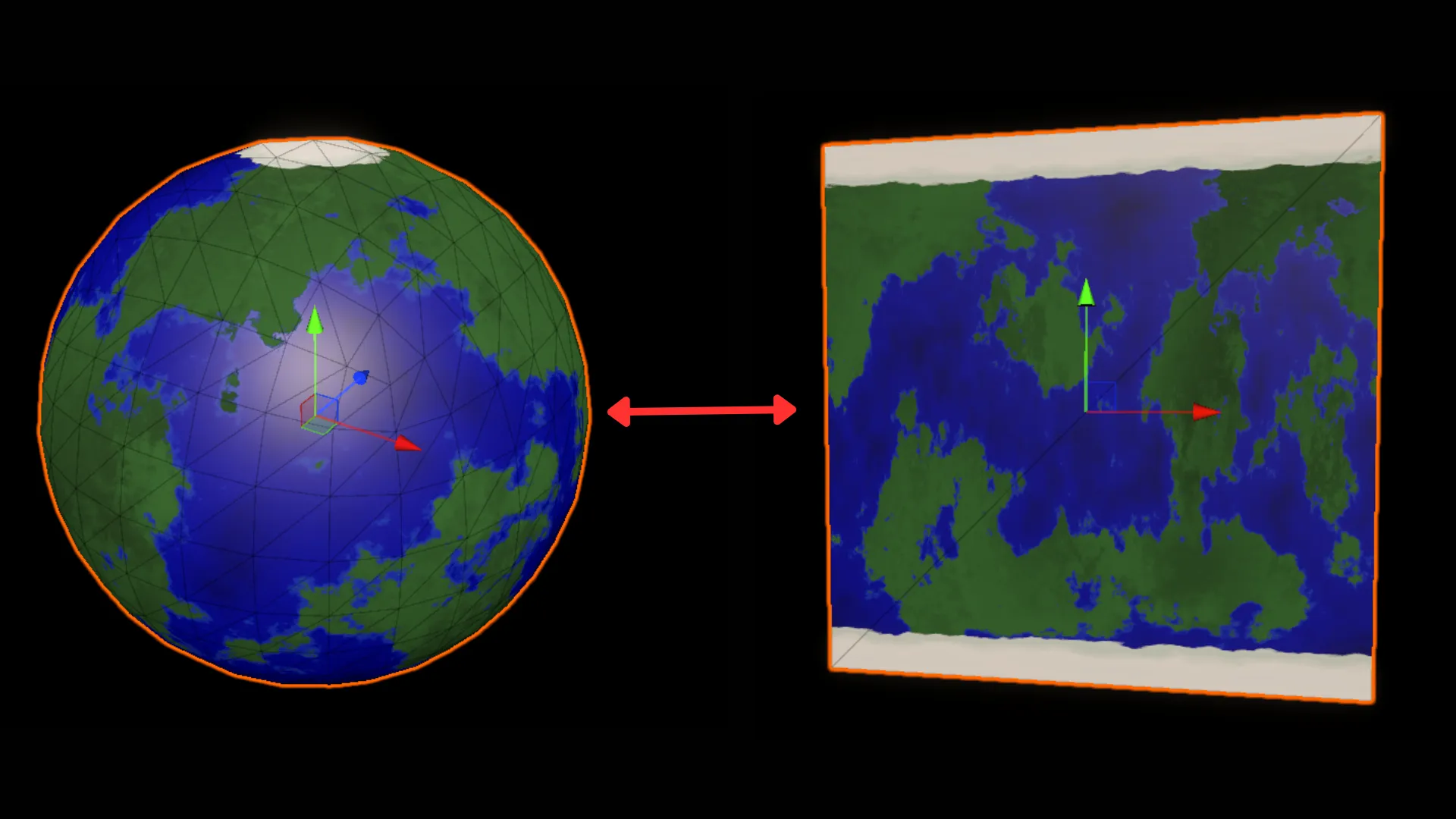
First, in order to bake the texture, we need to be able to convert 2D UV coordinates back into 3D positions on a unit sphere. With this, we can sample our 3D procedural noise functions with 2D UVs and store their outputs on a texture. The result is what’s called equirectangular projection (also known as a latitude-longitude projection) - the same projection used for world maps where the whole globe is unwrapped into a rectangle.
Understanding the UV-to-Spherical Conversion
We will achieve this conversion with simple trigonometry by isolating the different components of spherical coordinates. Keep in mind that on a unit sphere, x,y,z coordinates range from -1 to 1 - so we want to convert our UVs into direction vectors essentially.
For a detailed exploration of spherical coordinates and conversions, see scratchapixel’s article.
Here I’ll break down the math behind converting a 2D UV coordinate into a 3D position on a sphere:
1. We take the 2D UV coordinates from the quad. These are in the range [0,1] for both U and V. We convert them to spherical angles phi and theta.
This uses spherical coordinates, where any point on a sphere can be described using two angles:
- Phi (φ): The longitude angle, rotating around the vertical (Y) axis. Goes from 0 to 2π (0° to 360°)
- Theta (θ): The latitude angle, measured from the north pole down. Goes from 0 at the top (north pole) to π at the bottom (south pole)
float phi   = uv.x * 2.0 * PI;   // longitude: [0,1] → [0, 2π]
float theta = (1.0-uv.y) * PI;   // latitude: [0,1] → [π, 0]
Note that we actually flip θ through the V coordinate with (1.0 - uv.y). We want theta = 0 at the top (north pole), because we use cos(theta) below to map the y coordinate. cos(0) = 1, which corresponds to the top of the sphere, or the north pole.
2. Next, we convert these spherical angles into Cartesian coordinates (x,y,z) using:
dir = float3(
    sin(theta) * cos(phi),
    cos(theta),
    sin(theta) * sin(phi)
);
So X = sin(theta) * cos(phi) means “go sin(θ) distance from the Y-axis, in the direction of angle φ around the circle, specifically the X-component of that direction.”
And Z = sin(theta) * sin(phi) means “go sin(θ) distance from the Y-axis, in the direction of angle φ around the circle, but in the Z-component of that direction.”
For the Y component, cos(theta) represents the height, going from Y=1 at the north pole (theta=0) down to Y=-1 at the south pole (theta=π).
Essentially, cos(φ) and sin(φ) determine x and z components and sin(θ) matches the sphere’s radius based on the latitude (y-component).
We can implement this in a custom function node:
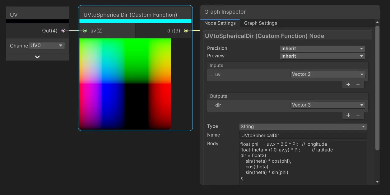
Note that PI is automatically defined in Shader Graph HLSL code.
And connect to the position input of our continent function: 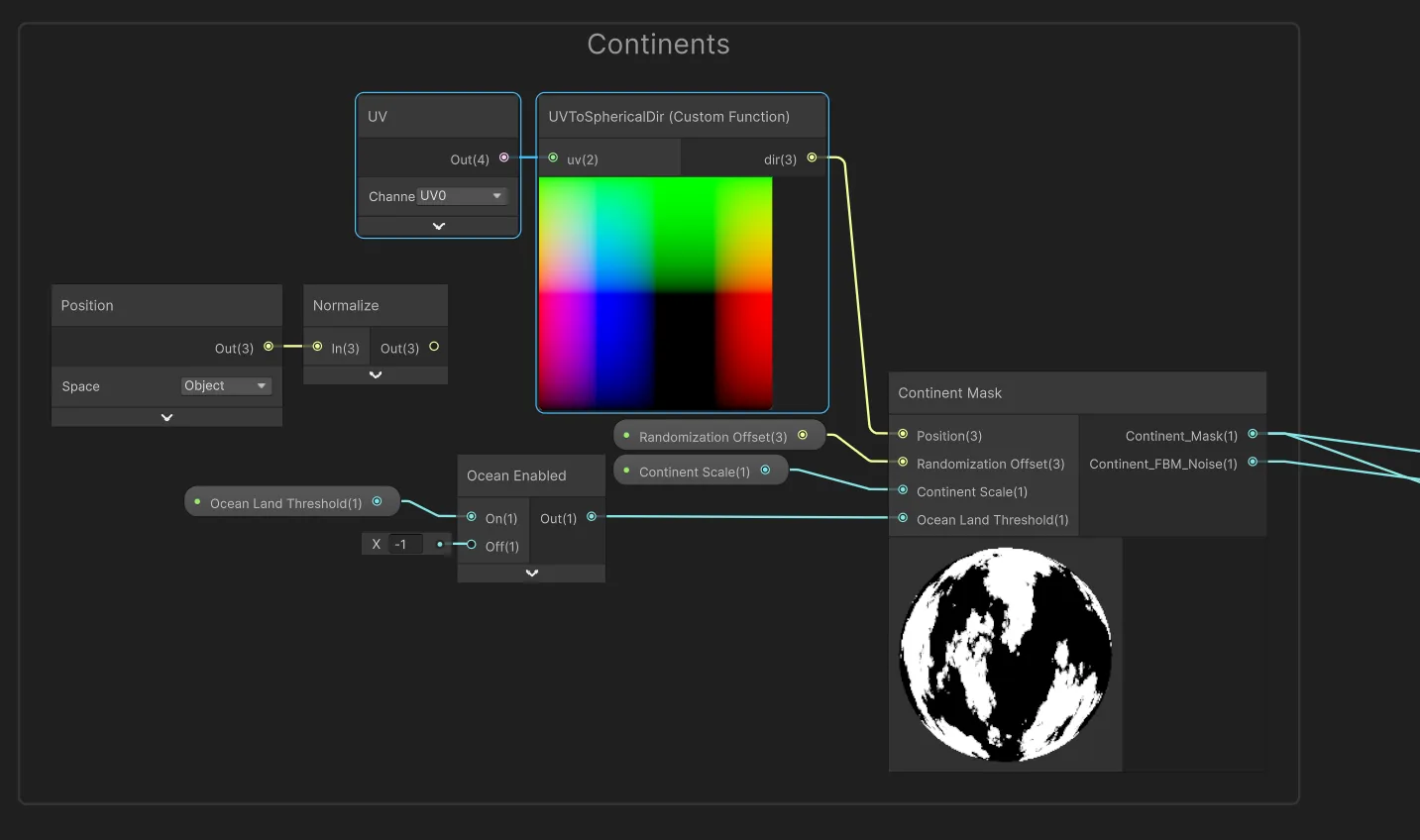
Now you should see the correctly unwrapped planet texture when viewing the quad: 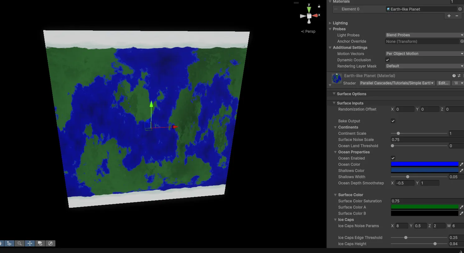
This will distort the spherical planet surface in turn, so next we will add a way to switch between input coordinates.
Adding Baking Mode to the Shader
We don’t want to always have UV input on in our shader, so we can add a boolean keyword that switches between the two modes. Add a Boolean Keyword property called “Bake Output” and use it to switch between using Object Position and UV-to-Spherical position:
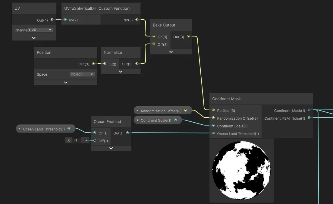
And then for all other terrain layer functions that use the position - oceans, ice caps, surface color: 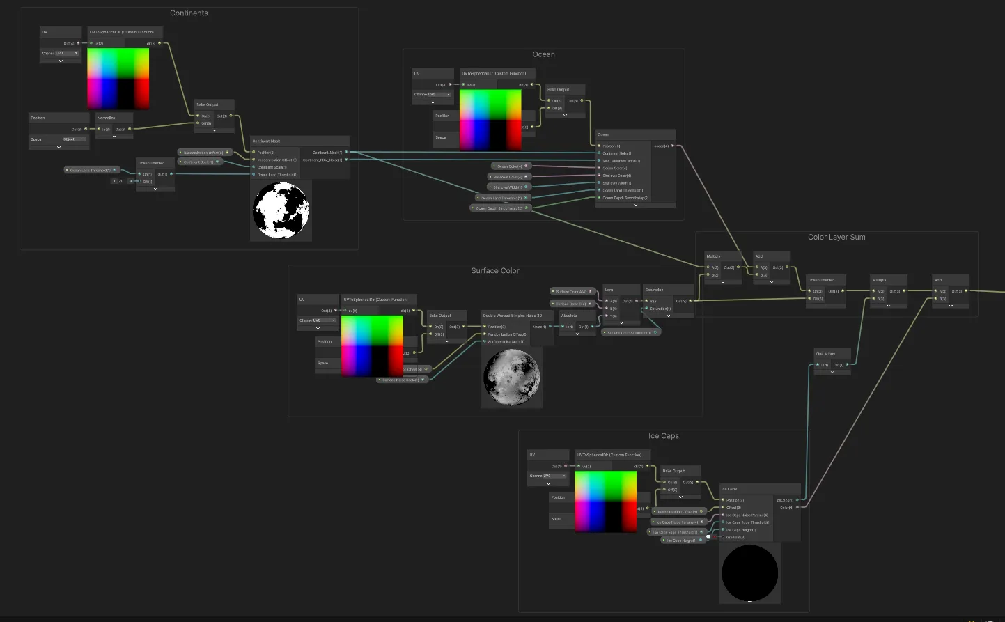
With this keyword we can switch between normal rendering mode and baking mode in the editor script we’re going to write later.
Emission Output
Finally for our shader, we want to use the Bake Output keyword to switch the shader color output to emission and disable the regular color contribution. This makes sure we get the correct color output when baking, without any lighting interference, like we would with an unlit shader: 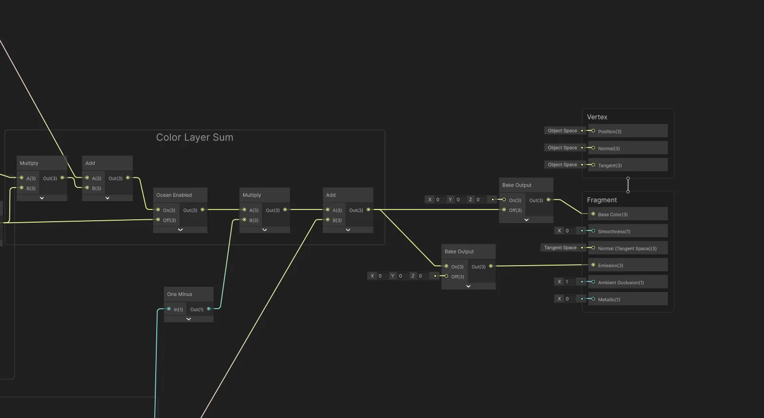
Setting up the Editor Script
Now that we have the shader set up to bake using UV coordinates, we need to create an Editor script that will render the material to a texture and save it to disk. For simplicity, we will use Unity’s MenuItem attribute to add a context menu option when right-clicking on the material in the Project window. If you wanted you could set up a Custom Editor window or Scriptable Wizard instead.
We create a new C# script called MaterialTextureBaker.cs. This will be an editor script, so make sure it is placed in an Editor folder:
using UnityEditor;
using UnityEngine;
using UnityEngine.Rendering;

public static class MaterialTextureBaker
{
    private const int k_resolution = 1024; // could be 512, 2048, etc depending on desired texture size

    [MenuItem("CONTEXT/Material/Bake Texture from Material")]
    private static void ContextMenuBakeTexture(MenuCommand context)
    {
        // Fetches the material you right-clicked on
        Material material = (Material)context.context;

        // Opens a save file dialog to select where to save the baked texture
        string savePath = EditorUtility.SaveFilePanelInProject("Save Texture","texture","png","");
        if (string.IsNullOrEmpty(savePath))
        {
            Debug.Log("No path selected!");
            return;
        }

        // Toggle the keyword to enable the correct baking output
        LocalKeyword kw = new LocalKeyword(material.shader, "_BAKE_OUTPUT");
        material.SetKeyword(kw, true);

        var textureToBake = TextureUtilities.GetTextureFromMaterial(material, k_resolution);

        TextureUtilities.SaveTextureAsPNG(savePath, textureToBake);

        // Assign default settings to the imported texture
        AssetDatabase.ImportAsset(savePath);
        TextureImporter textureImporter = AssetImporter.GetAtPath(savePath) as TextureImporter;
        if (textureImporter != null)
        {
            textureImporter.maxTextureSize = k_resolution;
            textureImporter.textureCompression = TextureImporterCompression.CompressedHQ;
        }
        AssetDatabase.ImportAsset(savePath, ImportAssetOptions.ForceUpdate);

        // Also need to perform cleanup
        Object.DestroyImmediate(textureToBake);
        AssetDatabase.Refresh();

        // Disable the baking keyword to restore the planet to normal rendering
        material.SetKeyword(kw, false);
    }
}
We also need to set up the TextureUtilities class:
To actually get a texture from a material, we can set up a temporary orthographic camera and put the material on a quad primitive mesh (this is just a plane with 4 vertices). We then render the camera to a RenderTexture and read back the pixels into a Texture2D. We use the quad primitive to actually have something in front of the camera to render, and this hold the material. The render texture holds the camera output so that we can read from it and save to disk.
We set up the color output of the shader to go to emission during baking mode earlier. In this utility we disable all other lights in the scene to avoid interference.
The camera is orthographic so that there is no perspective distortion.
public static class TextureUtilities
{
  public static Texture2D GetTextureFromMaterial(Material material, int textureSize)
  {
    // Will use render texture to capture camera output later
    RenderTexture renderTexture = RenderTexture.GetTemporary(textureSize, textureSize, 16);
    RenderTexture.active = null;

    // Temporary orthographic camera setup
    GameObject tempCameraObj = new GameObject
    {
        transform =
        {
            position = Vector3.back
        },
        hideFlags = HideFlags.HideAndDontSave
    };

    Camera tempCamera = tempCameraObj.AddComponent<Camera>();
    tempCamera.hideFlags = HideFlags.HideAndDontSave;
    tempCamera.enabled = false;
    tempCamera.cameraType = CameraType.Preview;
    tempCamera.orthographic = true;
    tempCamera.orthographicSize = 0.5f;
    tempCamera.farClipPlane = 10.0f;
    tempCamera.nearClipPlane = 0.1f;
    tempCamera.clearFlags = CameraClearFlags.Color;
    tempCamera.backgroundColor = Color.clear;
    tempCamera.renderingPath = RenderingPath.Forward;
    tempCamera.useOcclusionCulling = false;
    tempCamera.allowMSAA = false;
    tempCamera.allowHDR = true;

    int previewLayer = 31;
    tempCamera.cullingMask = 1 << previewLayer;

    tempCamera.targetTexture = renderTexture;

    //// Lighting setup
    // Need to disable all scene lights so they don't interfere with the material preview
    // Will re-enable them after rendering
    Light[] sceneLights = Object.FindObjectsByType<Light>(FindObjectsSortMode.None);

    foreach (var light in sceneLights)
    {
        light.enabled = false;
    }

    // Render the material on a temporary quad directly in front of the camera
    var tempQuad = GameObject.CreatePrimitive(PrimitiveType.Quad);
    tempQuad.GetComponent<MeshRenderer>().sharedMaterial = material;
    tempQuad.layer = previewLayer;
    tempCamera.Render();

    // Use a render texture to capture the camera output
    RenderTexture.active = renderTexture;
    Texture2D texture = new Texture2D(textureSize, textureSize, TextureFormat.ARGB32, false);
    texture.ReadPixels(new Rect(0, 0, renderTexture.width, renderTexture.height), 0, 0);
    texture.Apply();

    // Cleanup
    RenderTexture.active = null;
    RenderTexture.ReleaseTemporary(renderTexture);

    Object.DestroyImmediate(tempCameraObj);
    Object.DestroyImmediate(tempQuad);

    // Restore disabled scene lights
    foreach (var light in sceneLights)
    {
        light.enabled = true;
    }

    return texture;
  }
}
In the same static TextureUtilities class we want to add a simple method for saving a texture as a PNG:
public static bool SaveTextureAsPNG( string savePath, Texture2D tex)
{
    tex.Apply();
    byte[] data = tex.EncodeToPNG();

    if (data != null)
    {
        System.IO.File.WriteAllBytes(savePath, data);
        return true;
    }
    else
    {
        return false;
    }
}
With this we will have a new context menu item by right-clicking on the material and selecting “Bake Texture from Material”: 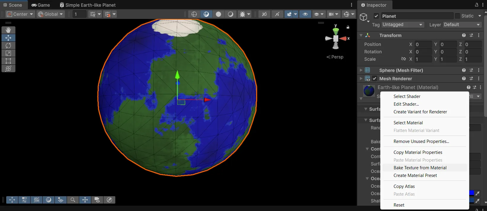
We can bake the texture and see that it looks like the quad output we saw earlier.
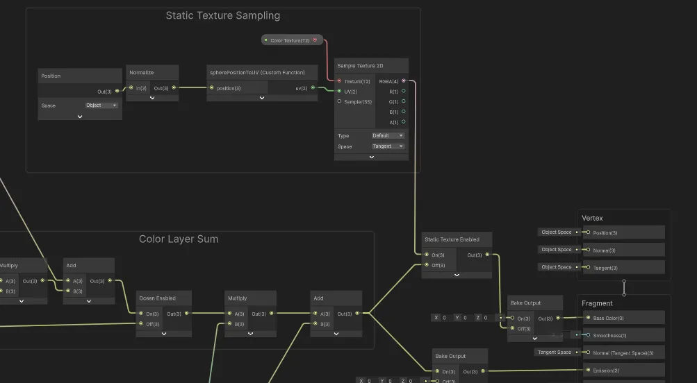
Sampling a baked texture in the shader
Now that we have a baked texture, we can modify our shader to sample from it instead of running the noise functions. We need to perform the opposite transformation of our earlier 3d-pos-to-spherical-to-uv transformation: We have a 2D texture to sample from, but we have a 3D sphere with object positions to sample with. So we need a conversion from 3D position to UV coordinates:
void spherePositionToUV(float3 position, out float2 uv)
{
    // sphericalCoord.x is azimuth in [-PI, PI], sphericalCoord.y is elevation in [0, PI]
    float2 sphericalCoord = float2(atan2(position.z, position.x), acos(position.y));

    // UVs need to be in [0,1] range
    float u = frac((sphericalCoord.x + PI) / (2.0 * PI) + 0.5f); // add 0.5 to rotate x to sync 3D position with baked texture orientation
    float v = 1.0 - (sphericalCoord.y / PI);

    uv = float2(u, v);
}
We can also set this up in a custom function node and connect it to a Sample Texture 2D node to get the color from the baked texture. Let’s also add another boolean keyword, “Static Texture Enabled,” to allow us to quickly switch between procedural and baked texture modes to compare performance and visuals:
And so we can switch between baked and procedural mode on our planet. Let’s compare the performance: 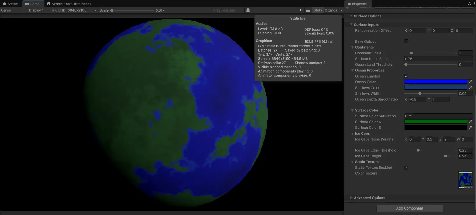 We can see we’ve doubled our framerate to 160 FPS/6 ms rendering time.
Blurry Textures
We can adjust the resolution of the baked texture to get more detail, in case the 1024x1024 texture is too blurry. But be wary of going too high and using too much memory for your textures. The baking time goes up quadratically with resolution as well.
Fixing the Seam
There seems to be an issue with a seam appearing on the planet at the location where the UVs wrap around from 1 back to 0. 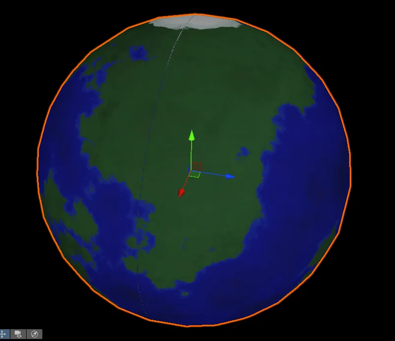
This is actually a common problem with sampling equirectangular textures, and its solution is straightforward and documented in the Shader Graph manual: https://docs.unity3d.com/Packages/com.unity.shadergraph@17.4/manual/Sample-Texture-2D-Node.html#example-graph-usage
We need to set the Mip Sampling Mode on our Sample Texture 2D node to Gradient: 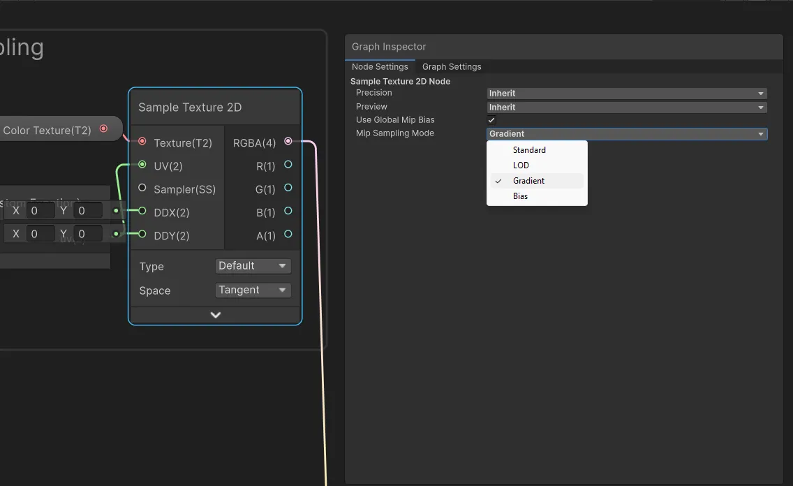
And connect our normalized position to the DDX and DDY inputs via DDX and DDY nodes: 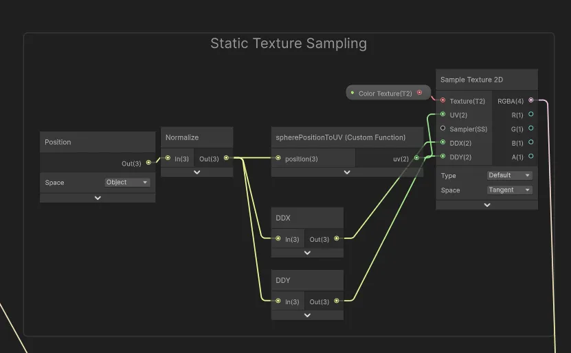
This fixes the seam problem and completes this part of the tutorial!
Conclusion
I’ve shown you one simple method to bake procedural planet textures inside the Unity Editor using a custom script. But there are still ways to improve this.
One problem that is very noticeable is the distortion at the poles of the planet, which is a common issue with equirectangular projections. You will have noticed how the poles are stretched out on the baked texture. They take up a lot more pixel area than they actually represent on the planet surface.
In practice, this makes the poles appear more clear and high-res compared to the rest of the planet, and consequently the equatorial areas look blurrier.
In the next tutorial, I will show you a method to bake textures using a cubemap projection instead, which addresses this issue: 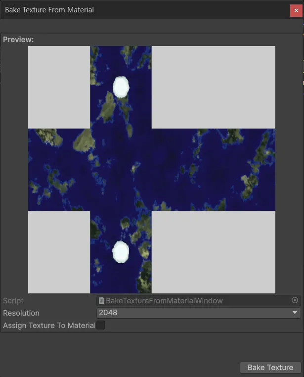
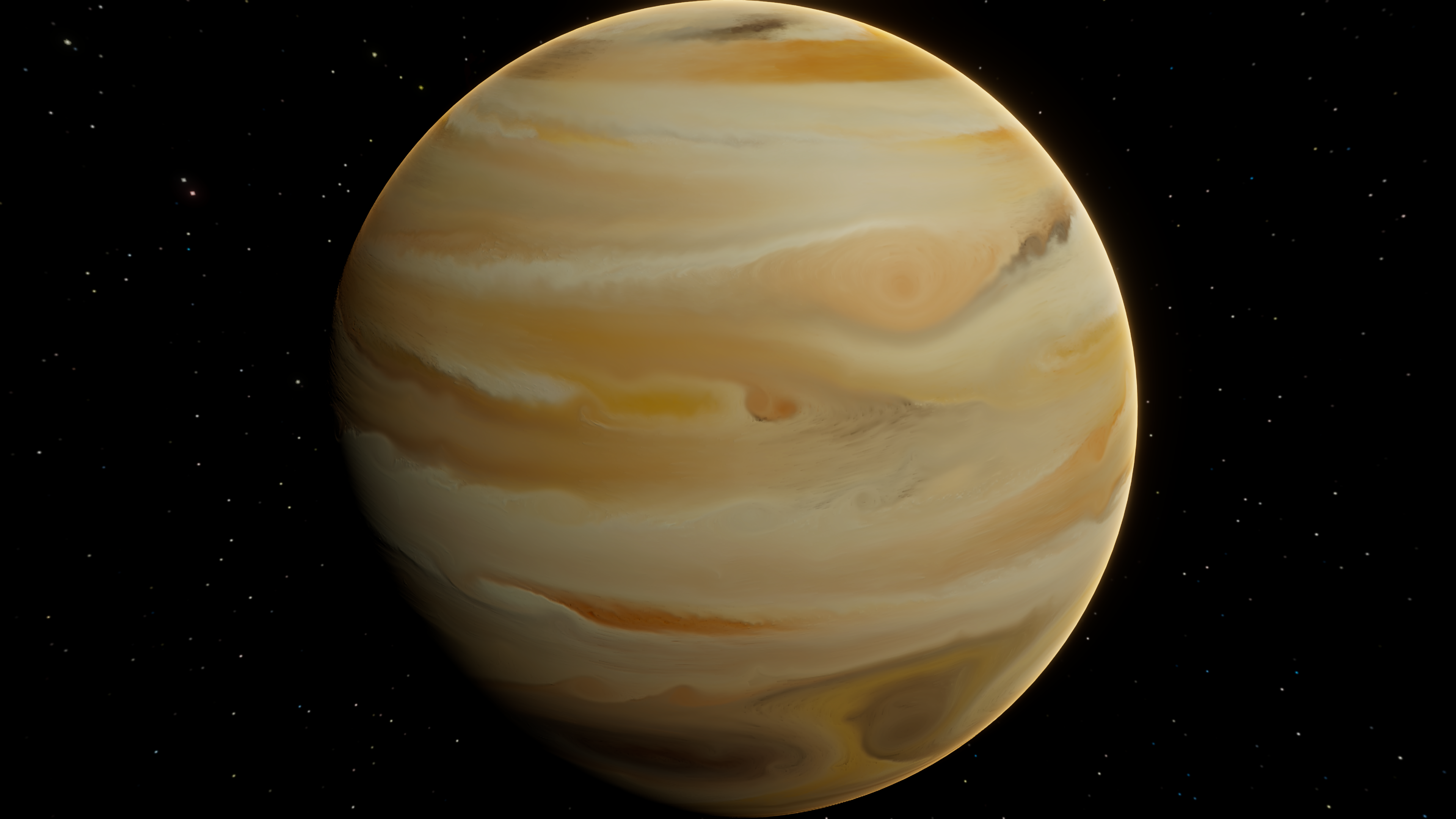
If you’d like to practice with more complex planet shaders, the Procedural Planet Generation Lite Samples asset is free on the Unity Asset Store and contains moons, more advanced Earth-like planets, gas giants, and stars.
If this tutorial was useful to you, and you would like to see more like it, consider supporting me on Ko-fi